Tadalafil gehört zur Gruppe der PDE5-Hemmer und wirkt über eine hochselektive Blockade des Enzyms Phosphodiesterase Typ 5. Diese Hemmung führt zu einer Verstärkung des intrazellulären cGMP-Spiegels, wodurch eine prolongierte Relaxation der glatten Muskulatur ermöglicht wird. Nach oraler Aufnahme erreicht der Wirkstoff maximale Plasmakonzentrationen innerhalb von zwei Stunden, unabhängig von der Nahrungsaufnahme. Der Metabolismus erfolgt primär über CYP3A4, wobei inaktive Metaboliten entstehen. Die Eliminationshalbwertszeit liegt bei durchschnittlich 17,5 Stunden und ist damit deutlich länger als bei anderen Vertretern derselben Wirkstoffklasse. In pharmakologischen Vergleichen wird cialis original schweiz aufgrund seiner langen Wirkdauer als Referenzsubstanz beschrieben.
232-237 boyes-varley
Surgical Modifications to the Brånemark
Zygomaticus Protocol in the Treatment of the
Severely Resorbed Maxilla: A Clinical Report
John G. Boyes-Varley, BDS, Dip Dent, MDent, FFD (MFOS)1/Dale G. Howes, BSc (Dent), BDS, MDent (Pros)2/
John F. Lownie, BDS, HDip Dent, MDent, PhD, FC MFOS3/Graham A. Blackbeard, BSc (Eng), MSc (Eng)4
Purpose: The Zygomaticus dental implant, designed by Nobel Biocare, was developed for the treat-ment of the severely resorbed maxilla. Brånemark has reported an overall success rate of 97.6% withthe placement of 183 implants over the last 12 years. The purpose of this article was to present amodification to the original Brånemark surgical approach to achieve better access and optimal implantplacement. Materials and Methods: There are parameters within the patient’s resorbed skeletalframe that guide the surgical placement of the currently used implant. However, there are shortcom-ings in the current surgical protocol. This report describes a simplified surgical approach in 45patients (77 implants) using an implant with a modified head angulation of 55 degrees and a place-ment appliance to assist the surgeon in placing the implant as close to the crest of the edentulousridge as possible. Results: The placement appliance identifies accurately the anatomic constraints ofthe resorbed skeletal frame that limit implant placement. This, together with the modified surgical pro-tocol, has resulted in improved access and in ideal positioning of the restorative head. Discussion: Thepresent technique allows restorative clinicians to achieve a more ideal restorative result in the poste-rior maxillary alveolus using the zygomatic implant, while reducing the buccal cantilever, improvingtongue space, and access for maintenance. Conclusion: By placing the implant closer to the crest ofthe alveolar ridge using the placement appliance and an implant with a 55-degree head, the emer-gence of the restorative head and resultant buccal cantilever can be reduced by as much as 20%. (INTJ ORAL MAXILLOFAC IMPLANTS 2003;18:232–237)
Key words: dental implants, maxillary sinus, zygomatic implants
To restore the severely resorbed maxilla with a implants.1–3 These bone-grafting procedures
fixed implant-supported prosthesis, extensive
include iliac crest bone grafts, which can be placed
bone grafting has been advocated to create adequate
onto the labial and buccal surface of the maxilla
bone volume for the placement of endosseous
(onlay technique),4 inlay grafts into the floor of themaxillary antrum,5 and Le Fort I maxillaryosteotomy with advancement and downgrafting
1Senior Specialist, Division of Maxillofacial and Oral Surgery,
techniques.6,7 The Le Fort I osteotomy also cor-
Department of Surgery, Faculty of Health Sciences, University of
rects the anteroposterior skeletal discrepancy asso-
the Witwatersrand, Johannesburg, South Africa.
2Senior Specialist, Department of Restorative Dentistry, School of
ciated with horizontal bone loss in the region of the
Oral Health Sciences, University of the Witwatersrand, Johannes-
labial plate and restores adequate bone volume to
accommodate implant placement into the maxilla.
3Chief Specialist and Professor/Head of Department, Division of
According to Rasmussen and coworkers,8 the
Maxillofacial and Oral Surgery, Department of Surgery, Faculty of
newly grafted maxilla should remain relatively load
Health Sciences, University of the Witwatersrand, Johannesburg,South Africa.
free for a period of 6 months to allow for consolida-
4Chief Executive Officer, Southern Implants, Johannesburg, South
tion of the grafted bone and to allow for revascular-
ization of the bone graft in the grafted sites. Implants may only be placed after a 6-month heal-
Reprint requests: Dr John G. Boyes-Varley, PO Box 87, Morning-side, Sandton 2057, South Africa. Fax: +27-11-784-6458. E-mail:
ing period. If this is done, Lekholm and associates
report that these procedures have a 76% to 84%
COPYRIGHT 2003 BY QUINTESSENCE PUBLISHING CO, INC.
PRINTING OF THIS DOCUMENT IS RESTRICTED TO PERSONAL USE ONLY.
NO PART OF THIS ARTICLE MAY BE REPRODUCED OR TRANSMITTED IN ANY FORM
WITHOUT WRITTEN PERMISSION FROM THE PUBLISHER. No. of Implants Placed by Type of Implant and Reconstruction Protocol Southern Southern Brånemark 55-degree head 45-degree head 45-degree head Reconstruction Implants Patients Implants Patients Implants Patients Implants Patients
success rate.9 This staged bone graft technique has
ships and amount of residual bone available for
increased treatment time, which is sometimes a
implant placement into the maxilla and zygoma.
tedious and socially unacceptable period for the
Finally, articulated diagnostic casts are used to
define any skeletal discrepancy between the maxilla
The advent of the zygomatic implant has pro-
vided the clinician with an alternative to grafting
Optimal surgical placement of the zygomatic
procedures in the reconstruction of the severely
implant depends on the patient’s pre-existing bony
resorbed maxilla. Brånemark originally designed the
anatomy. The authors, in treating 45 patients using
technique in 1989 and since then has reported a
the Zygomaticus protocol (Table 1), have identified
total of 164 implants placed into 81 patients, with
2 basic facial skeletal forms associated with severe
an overall success rate of 97% since inception of
maxillary bone loss. This may be the result of nor-
this implant technique.10,11 Although the Zygomati-
mal physiologic bone resorption, traumatic bone
cus implant (Nobel Biocare, Göteborg, Sweden) has
loss associated with oncologic resection, or facial
had a remarkable success rate in the severely
gunshot wounds. Two facial forms are readily iden-
resorbed maxilla,12 there are shortcomings in both
tified using anteroposterior cephalometric radi-
the surgical and prosthodontic techniques as origi-
ographs, namely either a long, thin face or short,
The purpose of this article was to present a mod-
The placement of a zygomatic implant with a 45-
ification to the original Brånemark surgical
degree angulated head has a profound effect on
approach to achieve better access during the surgi-
both the emergence profile and buccal cantilever
cal procedure and decrease postoperative morbidity.
and may not be indicated for both facial forms.
Secondly, a proposed design of an appliance that
Thus, optimal placement of zygomatic implants is
may be used intraoperatively to assist the surgeon in
governed by patients’ pre-existing surgical anatomy.
accurately placing the implant in an optimal posi-
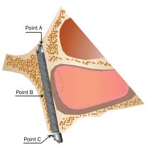
Optimal placement is dictated by the position of 3
tion on the edentulous ridge is described. It involves
the use of an implant with a 55-degree head angula-tion to decrease the buccal cantilever of the final
• The position of the zygomatic notch, ie, the
point where the forward projection of the zygo-matic arch meets the frontal process of the zygo-matic bone (point A)
• The confines of the lateral wall of the maxillary
• The thickness of the existing alveolar crest
There are many factors that contribute to the
optimal placement and ultimate long-term successof the zygomatic implant protocol. It is important
For optimal implant placement, the position of
to evaluate clinically the patient’s skeletal and facial
the zygomatic notch is very often non-negotiable
profile. This is followed by radiologic investigations
and provides the superior pivot point of the zygo-
to assess the horizontal and vertical jaw relation-
matic implant. In some instances, the surgeon can
The International Journal of Oral & Maxillofacial Implants
COPYRIGHT 2003 BY QUINTESSENCE PUBLISHING CO, INC.
PRINTING OF THIS DOCUMENT IS RESTRICTED TO PERSONAL USE ONLY.
NO PART OF THIS ARTICLE MAY BE REPRODUCED OR TRANSMITTED IN ANY FORM
WITHOUT WRITTEN PERMISSION FROM THE PUBLISHER.
Modified Zygomatic Implant ProtocolPatient Selection. The primary indication for thezygomatic implant protocol is the patient with aseverely atrophied maxilla. In some cases, initially aLe Fort I maxillary osteotomy and inlay bone graftmay be indicated. This procedure is then followedby zygomatic implant placement and restorationwith a fixed maxillary prosthesis. Unilateral recon-struction with zygomatic implants following toothloss, ablative surgery (ie, hemimaxillary defects), ortraumatic bone loss has also been performed usingthis technique.
Contraindications to the use of this technique
include patients with acute or chronic sinusitis withmucosal hypertrophy. These patients need to be ini-tially managed conservatively by first eliminating thesinus disease prior to zygomatic implant placement. Patient Preparation. The placement of zygomatic
implants is performed under general anesthesia.
Optimal positioning of zygomatic implants.
Infiltration anesthesia with 8 mL of 2% lignocainewith 1:80,000 adrenaline is administered formucosal vasoconstriction. After completion of thesurgical procedure, infiltration of a longer-actinglocal anesthetic agent, 10 mL of 0.5% bupivicaine
place the exit point of the implant more medially,
with 1:200,000 adrenaline can be distributed sub-
toward the inferolateral orbital margin; however,
mucosally from the zygomatic buttress regions
great care should then be taken not to perforate the
bilaterally for postoperative pain control. Perioper-
bony orbit with subsequent disruption of the orbital
ative intravenous dexamethasone (16 mg) and intra-
contents. This allows for a more upright implant
venous amoxicillin (1.2 g) are administered.
position and brings the restorative head of the
Operative Technique. A crestal incision is made
implant into the first molar site rather than the sec-
extending from 1 cm anterior to the maxillary
ond premolar site, thus providing a more satisfac-
tuberosity to the same position on the contralateral
side. A 1.5-cm vertical releasing incision is made
The lateral wall of the sinus must be engaged as
bilaterally at the posterior extent of the incision in
far laterally as possible by the implant body to
the maxillary second molar region. A vertical inci-
obtain the most lateral position of the implant body
sion is made anteriorly in the region of the anterior
in the sinus. The exit point of the head of the
nasal spine to facilitate flap mobilization to beyond
implant in the maxillary alveolus should also be
placed as close to the mid-alveolar position of the
Periosteal elevation of this flap results in the
ridge as possible. This is achieved by placing the
same exposure as the traditional Le Fort I incision,
initial pilot drill hole as high up the ridge and as far
but with a less bulky palatal mass of tissue than that
laterally as the confines of the maxillary antrum will
associated with the Le Fort I incision. The dissec-
allow. This positions the implant platform as far
tion then extends around the base of the piriform
buccally into the crest of the ridge as possible. The
rim up to the inferior aspect of the infraorbital
use of a placement appliance can assist in the initial
nerves, and finally the inferior aspect of the body of
placement of the pilot drill in the palatal alveolar
the zygoma bilaterally, as is described in the original
bone (Southern Implants, Irene, South Africa) (Fig
2a). The placement appliance lines up the initial
The superior and lateral aspects of the zygoma
entrance hole of the implant preparation site in the
are exposed by a tunneling technique, and a cus-
palatal bone with the entrance hole into the body of
tom-designed retractor (Southern Implants) is
the zygoma at the superolateral aspect of the maxil-
placed into the zygomatic notch. This acts as a good
lary antrum. This assists the surgeon in placing the
guide for placement of the exit point of the implant
initial drill preparation site as far laterally into the
body at the superior aspect of the zygomatic bone.
alveolus as possible and minimizes operator error,
A 0.12-inch round bur is then used to create a
which usually results from surgical inexperience.
lateral window in the superior wall of the antrum,
COPYRIGHT 2003 BY QUINTESSENCE PUBLISHING CO, INC.
PRINTING OF THIS DOCUMENT IS RESTRICTED TO PERSONAL USE ONLY.
NO PART OF THIS ARTICLE MAY BE REPRODUCED OR TRANSMITTED IN ANY FORM
WITHOUT WRITTEN PERMISSION FROM THE PUBLISHER.
Placement appliance to optimize implant placement.
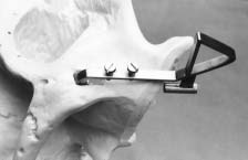
Placement appliance in situ on a model skull. The screw
at the end of the appliance is placed into the preparation site inthe zygoma. The tube guides the placement of the initial pilot inthe palate, allowing for optimal palatal placement.
taking care not to perforate the exposed sinusmucosa. The sinus mucosa is then reflected and,using a round bur, the proposed point of entry ofthe implant into the zygomatic bone is demarcatedthrough the sinus window. To place the head of theimplant as close to the crest of the edentulous ridgeas possible, the specially designed placement appli-ance is used for the initial pilot drill (Fig 2b). Thisallows for optimal placement of the implant head inthe alveolar crest, as far laterally to the crest of theridge as is possible. It not only decreases the unde-sirable buccal cantilever but also improves theemergence profile of the definitive prosthesis. Final
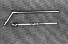
Implant analogs, which assist in choosing the best head
implant site preparation is achieved by enlargement
using graded pilot and twist drills. The authors pre-fer to place the exit point of the implant moremedially toward the inferolateral orbital margin. This allows for a more upright implant position andbrings the restorative head of the implant into thefirst molar site. Care should be taken to avoid per-
an implant with a 45- or 55-degree head is deter-
foration of the bony orbit and possible subsequent
mined with the aid of implant analogs (Southern
Implants) (Fig 3). The trial implant analogs are of
Modification to Implant Design and Placement.
varying lengths (between 35 and 50 mm), with head
In addition to the standard head angulation of 45
angulations of either 45 or 55 degrees placed into
degrees, an implant with a head angulation of 55
degrees has been designed (Southern Implants) to
To avoid the implant protruding too far out of
further improve the emergence profile and decrease
the lateral aspect of the body of the zygoma and
the buccal cantilever at the level of the occlusal
becoming palpable to the patient, an implant length
plane. An additional modification to the design of
that is 2.5 mm shorter than the estimated length
the implant is that it has been surface enhanced
should be chosen. Final placement of the implant is
(SLA) using a large-grit, acid-etched technique.14
accomplished using the standard protocol.11 To
The implant had been surface enhanced along the
achieve the appropriate angulation of the implant
entire length in order to maximize contact with the
platform, a hexagonal machine screwdriver is placed
bone, namely the body of the zygomatic bone, and
in the implant mount screw, and the implant is sub-
within the wall of the maxillary sinus wall and alve-
sequently adjusted so that the abutment is as paral-
olar bone areas. The decision as to whether to use
lel as possible to the implants in the canine sites.
The International Journal of Oral & Maxillofacial Implants
COPYRIGHT 2003 BY QUINTESSENCE PUBLISHING CO, INC.
PRINTING OF THIS DOCUMENT IS RESTRICTED TO PERSONAL USE ONLY.
NO PART OF THIS ARTICLE MAY BE REPRODUCED OR TRANSMITTED IN ANY FORM
WITHOUT WRITTEN PERMISSION FROM THE PUBLISHER. No. of Implants Placed by Type of Implant and Loading Period Southern Southern Brånemark 55-degree head 45-degree head 45-degree head Loading period Implants Patients Implants Patients Implants Patients Implants Patients
Thereafter, patients were followed up at 6-
month intervals and assessed for both clinical and
In this clinical study, the authors have treated 45
radiologic signs of implant loss or sinus pathology.
patients using the Zygomaticus implant protocol,
The authors report no implant loss at 30 months.
and a total of 77 implants have been placed (Table1). Of the 77 implants placed, 47 implants have 45-degree angulated heads and 30 implants have 55-
The first 10 implants were placed according to
The Zygomaticus implant has had a remarkable
the standard Brånemark surgical protocol and were
success rate in the treatment of the severely
45-degree Brånemark System implants (Nobel Bio-
resorbed maxilla. When compared to more conven-
care).11 The next 67 implants were placed according
tional treatment modalities advocated for maxillary
to the modified surgical protocol described above
reconstruction for the resorbed maxilla, the zygo-
and were placed with the aid of the placement
matic implant has the highest success rate of all of
appliance. These implants were either 45- or 55-
the traditional treatment modalities, despite the
degree angulation and were selected according to
small number of implants placed so far and the
the patients’ resorbed skeletal profiles.
short time that the implants have been loaded.9,10
The implants were exposed 6 months after place-
The authors and others have found that once the
ment, and an impression of the restorative head of
initially difficult surgical approach of the original
the implants was made by the prosthodontist at the
Brånemark protocol has been mastered, it can be
time of implant exposure. All 77 implants were inte-
simplified and the shortcomings of the surgical and
grated at the time of abutment and prosthesis place-
prosthodontic protocols circumvented.
ment and were subsequently loaded with a fixed or
The recommended Le Fort I incision provides
fixed/removable overdenture prosthesis. The oncol-
excellent buccal access to the nasal aperture and lat-
ogy and gunshot patients were reconstructed with a
eral aspect of the zygoma. This leaves a large palatal
Dolder bar and an overdenture, while the com-
mass of tissue, which has to be stripped over the
pletely edentulous and partially dentate patients
alveolar ridge and then retracted palatally for palatal
were reconstructed with fixed, screw-retained pros-
access and eventual palatal implant placement. The
authors suggest that a crestal incision circumvents
Patients were recalled 6 months after initial
this large palatal mass of tissue by the use of 3
implant loading, with the longest loading period in
strategically placed vertical incisions up into the
this study being 30 months (Table 2). Implant sur-
labial and buccal sulcus. This technique also allows
vival was assessed using the following criteria:
for a hemimaxillary flap that can be raised unilater-ally for placement of a unilateral zygomatic implant.
• Radiographs taken 6 months after implant load-
The sinus slot technique as described by Stella
ing revealed no residual sinus pathology or signs
and Warner13 mentions that perforation of the lat-
eral antral wall is not an important factor. The
• The implant-supported prosthesis had been
authors concur with Stella and Warner, in that if the
loaded for a minimum of 6 months, with no clin-
threads of the implant are slightly exposed outside
the confines of the lateral antral wall, the implant
COPYRIGHT 2003 BY QUINTESSENCE PUBLISHING CO, INC.
PRINTING OF THIS DOCUMENT IS RESTRICTED TO PERSONAL USE ONLY.
NO PART OF THIS ARTICLE MAY BE REPRODUCED OR TRANSMITTED IN ANY FORM
WITHOUT WRITTEN PERMISSION FROM THE PUBLISHER.
can be deemed to be optimally placed at the lateral
antral wall position. Stella and Warner also felt thatit was not necessary to make the buccal access win-
The authors wish to thank the staff at Southern Implants for
dow in the superolateral aspect of the maxillary
their technical help and Professor Peter Cleaton-Jones for hisassistance in the preparation of this manuscript.
antrum. However, the authors disagree with thesinus slot technique, since (1) it does not allowdirect visualization of the access point of the
implant into the body of the zygoma, and (2) perfo-ration of the posterior antral wall is possible
1. Keller EE, Tolman DE, Eckert SE. Maxillary antral-nasal
because of lack of visibility. This may result in
inlay autogenous bone graft reconstruction of compromised
either placement of the implant in the infratempo-
maxillae: A 12-year retrospective study. Int J Oral Maxillofac
ral fossa or introduction of muscle fibers into the
implant site. The latter could result in recurrent
2. Tolman DE. Reconstructive procedures with endosseous
implants in grafted bone. Int J Oral Maxillofac Implants
postoperative pain or nonintegration of the implant.
Good visibility of the maxillary antrum is especially
3. Report of the International Research Group on Reconstruc-
important when the implant is to be uprighted and
tive Preprosthetic Surgery Consensus Report. Int J Oral
placed more medially toward the inferolateral
4. Isaksson S, Alberius P. Maxillary alveolar ridge augmentation
with onlay bone grafts and immediate endosseous implants. J
A placement appliance has been proposed and
Craniomaxillofac Surg 1992;20:2–7.
designed to facilitate optimal implant placement
5. Jensen OT (ed). The Sinus Bone Graft. Chicago: Quintes-
closer to the crest of the alveolar ridge, thus
enhancing restorative potential. The use of this
6. Kahnberg KE, Nilsson P, Rasmussen L. Le Fort I osteotomy
apparatus has permitted a more predictable and
with interpositional bone grafts and implants for rehabilita-tion of the severely resorbed maxilla: A 2-stage procedure.
accurate approach to the surgical protocol and, in so
Int J Oral Maxillofac Implants 1999;14:571–578.
doing, has significantly decreased the risks associ-
7. Nystrom E, Lundgren S, Gunne J, Nilson H. Interpositional
ated with the long buccal cantilever that results
bone grafting and Le Fort I osteotomy for reconstruction of
from a palatal placement position. The long buccal
the atrophic edentulous maxilla. A two-stage technique. Int J
cantilever can be further reduced by the use of the
Oral Maxillofac Surg 1997;26:423–427.
8. Rasmussen L, Meredith N, Cho IH, Sennerby L. The influ-
modified implants, which have a 55-degree angula-
ence of simultaneous versus delayed placement the stability
of titanium implants in onlay bone grafts. A histologic andbiometric study in the rabbit. Int J Oral Maxillofac Surg1999;28:224–231.
9. Lekholm U, Wannfors K, Isaksson S, Adielsson B. Oral
implants in combination with bone grafts. A 3-year retro-spective multicenter study using the Brånemark implant sys-
Modifications to the surgical procedure for the
tem. Int J Oral Maxillofac Surg 1999;28:181–187.
placement of zygomatic implants has both short-
10. Brånemark P-I, Svensson B, van Steenberghe D. Ten-year
ened the operative time and postoperative morbid-
survival rates of fixed prostheses on four or six implants ad
ity for patients treated using this protocol. In addi-
modum Brånemark in full edentulism. Clin Oral ImplantsRes 1995;6:227–231.
tion, when the implant is placed closer to the crest
11. Darle C. Brånemark System, Nobel Biocare, ed 2. October
of the alveolar ridge using an adjunctive placement
2000. Nobel Biocare, Gothenburg, Sweden.
appliance and implants with either a 45-degree or
12. Jensen OT, Shulman LB, Block MS, Iacono VJ. Report of
55-degree head are used, the emergence of the
the Sinus Consensus Conference of 1996. Int J Oral Max-
restorative head can be optimized. This has resulted
13. Stella JP, Warner MR. Sinus slot technique for simplification
in the buccal cantilever being reduced by as much as
and improved orientation of zygomaticus dental implants.
20% in some patients,15 measured at the occlusal
Int J Oral Maxillofac Implants 2000;15:889–893.
plane. Modifications to the implant design, as well
14. Buser D, Schenk RK, Steinemann S, Fiorellini JP, Fox CH,
as surgical technique, have expanded the indications
Stich H. Influence of surface characteristics on bone integra-
tion of titanium implants. A histomorphometric study inminiature pigs. J Biomed Mater Res 1991;25:889–902.
15. Boyes-Varley JG, Lownie JF, Howes DG, Blackbeard GA.
Surgical modifications to the Brånemark zygomaticus proto-col [poster presentation]. European Academy of Osseointe-gration, Brussels, Belgium, 2002.
The International Journal of Oral & Maxillofacial Implants
COPYRIGHT 2003 BY QUINTESSENCE PUBLISHING CO, INC.
PRINTING OF THIS DOCUMENT IS RESTRICTED TO PERSONAL USE ONLY.
NO PART OF THIS ARTICLE MAY BE REPRODUCED OR TRANSMITTED IN ANY FORM
WITHOUT WRITTEN PERMISSION FROM THE PUBLISHER.
University of California, Irvine School of Medicine• Mr. C is a 92 year old man who lives in an apartment adjacent to his daughter’s house, with the assistance of a paid caregiver– Atrial fibrillation– Prostatic hypertrophy and an indwelling catheter– Osteoarthritis – Glaucoma– Congestive Heart Failure• He is responsible for taking his own Rx• Recently the CHF worsened and i
COMPANIES PRODUCING FORMULATED GRAIN-FRUIT PRODUCTS THAT MEET FNS SPECIFICATIONS FOR FORMULATED GRAIN-FRUIT PRODUCTS (7 CFR PART 220 APPENDIX A) Bake Crafters Associated Bakeries Apple Spice Muffin Hagerstown, MD 21742 Labels bearing the above product name will have the following ingredient statement: Enriched flour, sugar, apples, soy oil, whole eggs, water, non fat dr
 Modified Zygomatic Implant ProtocolPatient Selection. The primary indication for thezygomatic implant protocol is the patient with aseverely atrophied maxilla. In some cases, initially aLe Fort I maxillary osteotomy and inlay bone graftmay be indicated. This procedure is then followedby zygomatic implant placement and restorationwith a fixed maxillary prosthesis. Unilateral recon-struction with zygomatic implants following toothloss, ablative surgery (ie, hemimaxillary defects), ortraumatic bone loss has also been performed usingthis technique.
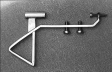
 Placement appliance to optimize implant placement.