Tadalafil gehört zur Gruppe der PDE5-Hemmer und wirkt über eine hochselektive Blockade des Enzyms Phosphodiesterase Typ 5. Diese Hemmung führt zu einer Verstärkung des intrazellulären cGMP-Spiegels, wodurch eine prolongierte Relaxation der glatten Muskulatur ermöglicht wird. Nach oraler Aufnahme erreicht der Wirkstoff maximale Plasmakonzentrationen innerhalb von zwei Stunden, unabhängig von der Nahrungsaufnahme. Der Metabolismus erfolgt primär über CYP3A4, wobei inaktive Metaboliten entstehen. Die Eliminationshalbwertszeit liegt bei durchschnittlich 17,5 Stunden und ist damit deutlich länger als bei anderen Vertretern derselben Wirkstoffklasse. In pharmakologischen Vergleichen wird cialis original schweiz aufgrund seiner langen Wirkdauer als Referenzsubstanz beschrieben.
Fuji-xerox xp-15/20 toner cartridges
New Arrivals! Company Info Publications Special Features Contact Us Overview Re-assemble the Toner Supply Chamber, OPC Required Tools Drum and Debris Cavity Required Supplies Clean the Printer Transfer Corona Wire Assembly Prepare Work Area Trouble Shooting Disassembly Test Prints Remove the OPC Drum Recommended Supplies Cleaning the Debris Cavity Cleaning the Toner Supply Housing Fuji-Xerox XP-15/20 Toner Cartridges DOC-0219 OVERVIEW
These instructions cover the recharging of the Fuji-Xerox XP-15/20 toner cartridge used in the Compaq PageMarq series, theDataproducts LZR-1500 series, and other printers using the Fuji Xerox XP-15/20 Laser Engine. These printers print on 11x17"paper, and have a resolution of 800 x 400 Dpi. Since the paper used in these machines is wider than “normal” 8 1/2 x 11"cartridges (SX Etc.), this cartridge is also wider (by about 4 inches). If 8 1/2 x 11" paper is used, you will notice that the paper isejected from the printer sideways. Keep this in mind when examining test prints because marks that would normally be in avertical pattern, will now be horizontal.
The purpose of this disassembly procedure is to vacuum out toner that will have spilled inside the cartridge during shipping and/or rough handling, to clean the debris cavity, and to clean and fill the supply chamber with new toner. This disassemblyprocedure should also be used to examine the internal parts of the cartridge for possible damage, or wear should the printing ofthe cartridge be poor and not correctable by any other means.
NOTE: These Instructions should be read completely before proceeding with the recharge.
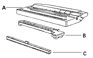
In order to properly recharge this cartridge you must obtainthe following three items from your customer.
A) 1- XP-15/20 Toner cartridge B) 1- Printer Transfer Corona Assembly C) 1- Felt wand
REQUIRED TOOLS
Phillips head screw driver. Small Common Screwdriver Pin Pulling Pliers 35 Watt Pen type soldering iron (Optional) Toner approved vacuum Needle Nose Pliers Razor Blade
REQUIRED SUPPLIES
Black Toner 730 Grams Sealing Strip Wiper Blade OPC Drum (Optional) Recovery Blade (Optional) Replacement Primary Corona wire Replacement Transfer Corona wire Felt Wand Rubber Cleaner or “Fantastic” Spray cleaner Cotton Swabs Lint Free Cotton Pads Toner Magnet 99% Isopropyl Alcohol Clean compressed air White Lithium or HP’s Conductive grease Scotch Tape
WARNING:Always wear safety goggles and breathing mask when working with or around toner. Do not disperse the toner into the air. Use approved toner vacuums and filters at all times. Approved Vacuum systems: Toner approved vacuum. The Atrix HCTV canister type toner vac, OR the Atrix AAA portable style vacuum. Some type of approved toner vacuuming system is important because toner consists of very fine particles that will pass right through a normal vacuum filter, and blow out the exhaust. PREPARE WORK AREA
1. Before proceeding with the following procedure you should have a work area available with approximately 4' x 3' clear
space. It should be covered with some disposable paper since toner will spill on this area. It is recommended thatbrown craft paper be used and taped to the work area. This will hold the paper in place when trying to vacuum tonerfrom the paper.
2. A garbage can with a strong plastic liner should be adjacent to the work area to empty used toner. It should be at least
2' deep to prevent toner from clouding up and over the top of the bag during disposal.
3. Have a few rags available and some disposable paper towels. TM-1 Toner Magnets are perfect for this.
4. The work area should be capable of being ventilated, if by accident toner becomes dispersed into the air. An exhaust
fan in one window is recommended for ventilation.
If the circulation of air in the work area room is combined with other rooms in the building, toner dust may be carriedinto the other rooms. A separate and isolated HVAC system is recommended for the work area room. DISASSEMBLY
1. The top cover is held on by two Phillips head screws, one on each side. Remove these two screws, and lift off the top
2. On one end of the Primary Corona Wire Assembly there is a small capacitor that is attached to the cartridge with a
Phillips head screw. Carefully remove this screw, and bend the lead out of the way.
NOTE: The other end of this Varistor is soldered to the corona wire frame. If you are not careful the soldered joint will break. If it does break or come loose, re-solder it using a 35 watt pen type soldering iron. Use only enough heat to flow the solder, if too much heat is used, you will damage the Varistor.
3. Remove the Primary Corona Wire Assembly by pulling the right side straight out, and to the right. Be careful not to
damage the small pin on the left. Place this assembly aside.
REMOVE THE OPC DRUM
1. On each side of the cartridge there is a spring, a large one on the left, and small on the right. Remove each spring.
These springs connect between the drum axle pin and the cartridge housing.
2. On the right side of the cartridge there is a metal drum axle pin held in by a Phillips head screw. Remove this screw
and the pin. Note that the pin has a small amount of light grease on the side. Pay careful attention to the location of thegrease, so that it can be replaced later.
3. Remove the two hinge pins that the two halves rotate on. These pins resemble the plastic pins found in the Canon
LBP-CX & SX cartridges, and can be removed in the same manner. SX pin pulling pliers work fine on these.
4. Carefully remove the OPC drum, being very careful not to scratch it. Vacuum any remaining toner and debris from the
drum, being very careful not to come into contact with the drum surface. Do not polish or wipe the drum with a dry cloth,since this may scratch the drum. Blow off any remaining dust using a can of compressed clean air. Never use un-filtered compressed air for this as un-filtered air will have small dirt particles which blown at high speeds, will damagethe drum.
CAUTION: When using the Compressed clean air, be very careful not to tilt or shake the can while spraying, as the propellant may spray out of the can and possibly ruin the drum.
5. Place the OPC Drum in a soft lint free cloth and then into a dark colored bag, or cover from bright light by some other
suitable means. Again, do not rub or wipe the OPC Drum with a dry cloth as this may scratch its surface. If there is anymatter left on the drum that must be cleaned off, use 99% pure Isopropyl Alcohol (FR-8), and a soft lint free cotton pad(PW-96) to lightly wipe the drum surface. Vacuum and then blow off the Drum using the Compressed Air. Alwayshandle the OPC drum with the utmost caution, since if damaged it cannot be replaced.
CLEANING THE DEBRIS CAVITY
Remove the two screws on either end of the Wiper Blade, and carefully pry it off. On some older cartridges, there is a strip ofscotch tape along the base of the wiper Blade. Cut this tape with a razor blade and remove. Dump any remaining toner into thegarbage and vacuum thoroughly. Before replacing the wiper blade, wipe it off with a TM-1 Toner Magnet, and coat lightly withthe drum padding powder (DPP). If the blade had tape on it remember to replace it.
WARNING: Be very careful not to bend or otherwise damage the small thin recovery blade located next to the Wiper Blade. If this blade is bent down lower than the height of the wiper blade, toner will accumulate on top of the blade and spill into the printer. If the blade does get bent, it may be possible to carefully bend the blade to a height equal to, or slightly higher than the Wiper Blade. Make sure that the edge of this blade is even across its entire length. CLEANING THE TONER SUPPLY HOUSING
1. Pull out the fill plug located on the right side of the toner supply. Dump out any remaining toner, and vacuum clean.
NOTE: Before vacuuming, rotate the magnetic roller by turning the Mid-sized gear on the right side of the cartridge. The roller will be very hard to turn, and using this gear will make it a little easier. When rotating the Magnetic roller, observe the layer of toner on the roller surface. The toner should form an even consistent layer with no clumps or lumps showing. Should the layer of toner be thicker in some areas, the Magnetic Roller should be cleaned using a dedicated magnetic roller cleaner.
Always remove the roller before cleaning and make sure it is completely dry before re-installing it. While vacuumingthe chamber out pay special attention to the small metal contact located on the left side of the toner supply. Make surethat it is firmly in place, and does not fall off, or come loose.
2. At this point there if you are going to ship the cartridge, a seal must be installed. To Install the seal, first remove the
Magnetic Roller, Doctor Blade and place aside. Do not place the Magnetic Roller near any metal objects, as they maycause damage to the roller.
3. On the left side of the Toner Supply cavity, there is a White Plastic Seal Pad. Remove this pad by sliding it out to the
4. On the left side, carefully lift the Magnetic Roller Felt up and away from the casing, just above where the White Plastic
Seal Pad was located. Do not Completely remove the felt, just lift it up.
5. From the right side, pull the thin metal bar out of the cartridge.
6. Take the Seal, and remove the self-adhesive backing.
7. Align the Seal Plate with the Pull Tape to the right. Slide the back edge of the seal into the back edge lip of the Supply
8. Press the seal into place. Make sure that all sides (Front, Back, Left, Right) are flat. If any areas are not flat, press
them down. If the seal does not lie flat it will leak. Remove the seal, locate the problem, and start over.
9. Take the Loose end of the Pull Tape and insert it under the felt on the left side. Position the Pull Tape so that it is flat in
10. Slide the White Plastic Seal Pad back into place. This pad is inserted on top of the Pull Tape. Make sure the entire
length of the Pull Tape is flat and not twisted.
11. Push the Magnetic Roller Felt back into place.
12. Re-install the long this metal bar, Make sure that the left side fits into the white plastic seal pad. NOTE: If you wish to test the cartridge after it is finished, save a little toner from the bottle, (We use the cap from the toner bottle). Sprinkle the toner along the Magnetic Roller. This will give you just enough to print a few test pages , with little or no toner in the Waste Bin.
Vigorously shake the bottle of toner until the toner moves freely. Pour the new toner into the Supply Chamber, andreplace the fill plug. Make sure that the plug is fully seated, and that there are no leaks.
RE-ASSEMBLE THE TONER SUPPLY CHAMBER, OPC DRUM AND DEBRIS CAVITY
1. Remove the drum from storage, coat the drum with the drum padding powder and replace in the Debris Cavity. Also
remember to clean off and replace the grease on the drum axle pin. You can use white lithium grease, or if you do laserrepairs and have HP’s conductive grease on hand, that will work as well. Make sure that you only put as much on asyou took off, and that you replace the grease only in the areas that initially had it.
2. Take out the Primary Corona Wire Assembly. If there is any loose toner in the assembly blow it off with a can of clean
air. Be certain to blow away from yourself. To get at the Corona Wire, the grid must be removed. To do this pry up ateach of the tabs, and lift the cover off. Once the grid has been removed, clean the Corona Wire with the IsopropylAlcohol, and a cotton swab. Run the swab carefully along the wire and the wire guides. Be very careful not to break thisfragile wire. If you are experiencing black streaks on the paper, the corona wire should be replaced by unhooking theold, and stringing the new one across. Be very careful when handling this wire as it is very fragile, and is easilycrimped. Replace the corona wire assembly by reversing step 3.3.
3. Re-assemble the cartridge by reversing steps 3.1 to 4.3. Pay careful attention to the Varistor on the corona wire
assembly, so that it doesn’t become damaged. Remember, if the solder connections do become damaged, they willhave to be re soldered. When soldering, keep the tip of the iron on the joint only long enough for the solder to flow. Iftoo much heat is applied, the Varistor will probably be damaged. Keep in mind that a cartridge that has severestreaking problems may also have a bad Varistor in addition to the Primary Corona Wire. CLEAN THE PRINTER TRANSFER CORONA WIRE ASSEMBLY
1. Clean the Transfer Corona Wire assembly. If any excess paper dust or toner is in the assembly, blow it out with a can
of compressed air, and clean with 99% pure Isopropyl Alcohol (FR-8) and a cotton swab. Do not use high pressure air(a Compressor) to blow this assembly out as it may break or damage the corona wire. Damaged wires can be replacedby re-stringing the wire. Again, be very careful when handling these wires as they are easily damaged.
2. If the registration roller is also dirty (the long skinny black roller next to the corona wire), it should be cleaned using a
lint free cotton pad dampened with “Fantastik” spray cleaner, or a rubber cleaner. DO NOT use alcohol as this will dry up the roller and cause it to crack. Store this assembly in a clean plastic bag. Re-felt the fuser wand. If the wand was not included, replace with a new wand. TROUBLE SHOOTING
Before taking any test prints, there are a few items in the printer that should be checked to ensure optimum print quality. Ifthese items are not maintained, they could cause print defects that may be incorrectly blamed on the cartridge.
Transfer Corona Wire Assembly; In the base of the printer, there is the Transfer Corona wire assembly. This assembly has what looks like fishing line at angles across the top. The Corona wire is actually under these angled wires, and runs straight across from left to right. This wire should be cleaned with a cotton swab, slightly dampened with alcohol. If this wire is dirty, the print outs will either be light, or have blank horizontal stripes. This assembly is provided with a new toner cartridge and is easily removed by pulling up on the right side. Make sure that you turn the power off before removing this assembly. Since these assemblies are provided with new cartridges, you should make sure that your customer provides the used assembly when turning the cartridge in for recycling. Fuser Assembly; Towards the front of the printer is the Fuser Assembly. This assembly has a felt wand that is used to keep the upper fuser roller clean. this wand should be replaced (or re-felted) every time the toner cartridge is replaced. Upper Fan Screen; In the top left side of the printer is the upper fan. This fan removes the air from the printer. In the top lid above the fan is the fan grid. This grid must be kept clean to allow the air to circulate. This printer does not use an ozone filter to trap ozone and
dust. The manufacturer states that the ozone emissions are low enough that it is not required. All of these items just covered,as well as the condition of the toner Cartridge effect the print quality, and should be checked before taking test prints. TEST PRINTS
To run a test print,(this is for a Compaq PageMarq 15 or 20 only) turn the printer off-line, and press the menu key on the frontpanel. the display will read: Language = English. Press the down arrow until the display reads: Print Reports. Press the enterkey. The display will read Font report. Press the down arrow key, the display reads H/W Report. Press the Enter key, the displaywill read “Printing”, and the page will print out. We recommend that 3-4 pages be run so that any defect patterns will be easilyvisible. Notice that the paper is ejected sideways from the printer, which matches how the paper is stored in the paper tray.
Once you have the print out’s, they need to be examined to determine possible cartridge defects. In general, any marks on thepaper that shouldn’t be there indicate a problem. We also examine print areas for abnormalities such as light print, poor blackfills and print inconsistencies. This printer can print using 11 x 17", or 81/2x 11 paper. When using 81/2 x 11" paper the paper isfed sideways, so that what normally would be vertical marks will actually be horizontal in the printout. Some of the morecommon toner cartridge problems are:
A Dirty Primary corona wire will show as random dark black streaks across the test page in the direction of paper travel. Thiswire is located the toner cartridge.
A Scratched drum shows up as a very thin, perfectly straight line that runs across the test page. Again this will be in thedirection of the paper travel.
A Chip in the drum will show as a dot that repeats 1-2 time per page. Any drum defects will repeat 1-2 times per page based onthe drum circumference of 4.8" and a page size of 81/2 x 11". It is for this type of defect that we recommend you run 3-4 testprints. Due to the drum circumference of 4.8" a chip may show up on the first page 1 time and on the next page twice. Itdepends where the damaged section of the drum is when the print cycle starts. Light damaged drums show up as a shaded area on the test print that should be white. Again this can will repeat 1-2 times perpage.
A Bad wiper blade will show as either a gray line approximately 1/8" thick, or as shading across the entire page. In either casethere will be a film of toner on the drum surface.
A Bad or un-connected Primary Corona Wire Varistor will show up as a series of oval marks throughout the page. They canalso appear as what might look like a bunch of grapes, or if your cartridge is streaking and you changed the Primary coronaWire, the Varistor should also be changed.
The toner cartridge printing process is best explained as a series of steps, or stages. (See the following diagram) The firststage in the printing process is the conditioning stage. This is where the Primary corona wire places a uniform negative DCcharge on the OPC drum surface. In the second stage (also called the imaging section), the laser beam is fired onto the OPCdrum surface. The laser beam dissipates the OPC drum charge to ground wherever it strikes the drum, leaving a latentelectrostatic image. The OPC drum’s circumference is 4.8" and therefore makes approximately 1.7 revolutions per 81/2 x 11page. The third or developing stage is where the image is developed on the drum by the developing section, or supplychamber. The supply chamber consists of the magnetic roller sleeve, DR blade, stationary magnet inside the roller, and manyother smaller parts. Simply put, the toner is held to the magnetic roller by the stationary magnet inside the sleeve, and avariable DC bias voltage supplied by the high voltage power supply. The variable DC bias voltage is controlled by the printerintensity dial. The amount of toner on the roller is controlled by the DR blade and by a static charge. The static charge iscaused by the toner moving between the Magnetic roller sleeve, and the Doctor blade. This charge also allows the toner toeasily transfer to the OPC drum. As the laser exposed areas of the OPC drum approach the magnetic roller, the toner particlesare attracted to the OPC drums surface due to the opposite voltage potentials of the statically charged toner, and laser exposedsurface of the OPC drum. This image is then transferred to the paper as it passes below the drum by the transfer corona wire,which places a positive charge on the back of the paper. This positive charge causes the negatively charged toner on thedrums surface to be attracted to the page. The static charge eliminator then removes any residual charges from the paper,which prevents the paper from sticking to the OPC drum. The image is then fused on to the paper by the fuser assembly, whichis comprised of both the upper and lower fuser rollers. The lower fuser roller presses the page up into the upper fuser rollerwhich then melts the toner into the paper. As the upper fuser roller turns, any excess toner is cleaned off by the felt wand. Thefinal or cleaning stage is where the OPC drum is cleaned. On average, approximately 90% of the toner is transferred to thepaper during the print cycle. The remaining 10% is cleaned off the OPC Drum by the wiper blade, guided into the wastechamber by the recovery blade, and stored in the waste chamber. The packing blade inside the waste chamber makes surethat this stored toner is kept away from the wiper and recovery blades, preventing any back-ups of waste toner. The eraselamps are then turned on and coat the OPC drum in a red light that neutralizes any residual charges from the drum. The OPCdrum is now ready to be conditioned by the Primary Corona Wire, and start the print cycle again.
2003 Summit Laser Products, Inc. Any attempt to reproduce any part of these instructions without the written consent of Summit Laser Products, Inc is prohibited. All registered trademarks are the property of their respective owners. RECOMMENDED SUPPLIES
Microsoft OLE DB Provider for ODBC Drivers error '80004005'
[Microsoft][ODBC Microsoft Access Driver]General error Unable to open registry key 'Temporary (volatile) Jet DSNfor process 0x3464 Thread 0x1874 DBC 0x8473d24 Jet'.
Private Security Industry Regulatory Authority The Director, Private Security Industry Regulatory Authority, Private Bag X817, PRETORIA, 0001 REQUIREMENTS TO REGISTER A BUSINESS as at 01 June 2012 Manual of Information to be purchased on registration ( please familiarize yourself with the Act and Regulations – IGNORANCE OF THE APPLICABLE LEGISLATION IS NOT AN EXCUSE) - R150.
Riccardo Primo, Re D’Inghilterra Libretto di Paolo Antonio Rolli, adattato da "ISACIO TIRANNO" di Francesco Briani Londra, 11 novembre 1727 Musica di George Frederich H andel Personaggi: Riccardo Primo, Re d'Inghilterra Costanza, principessa di Navarra, sua promessa sposa Berardo, cugino e tutore di Costanza Isacio, tiranno di Cipro P


 New Arrivals!
 Black Toner 730 Grams Sealing Strip Wiper Blade OPC Drum (Optional) Recovery Blade (Optional) Replacement Primary Corona wire Replacement Transfer Corona wire Felt Wand Rubber Cleaner or “Fantastic” Spray cleaner Cotton Swabs Lint Free Cotton Pads Toner Magnet 99% Isopropyl Alcohol Clean compressed air White Lithium or HP’s Conductive grease Scotch Tape
WARNING:Always wear safety goggles and breathing mask when working with or around toner. Do not disperse the toner into
Black Toner 730 Grams Sealing Strip Wiper Blade OPC Drum (Optional) Recovery Blade (Optional) Replacement Primary Corona wire Replacement Transfer Corona wire Felt Wand Rubber Cleaner or “Fantastic” Spray cleaner Cotton Swabs Lint Free Cotton Pads Toner Magnet 99% Isopropyl Alcohol Clean compressed air White Lithium or HP’s Conductive grease Scotch Tape
WARNING:Always wear safety goggles and breathing mask when working with or around toner. Do not disperse the toner into

 REMOVE THE OPC DRUM

 8. Press the seal into place. Make sure that all sides (Front, Back, Left, Right) are flat. If any areas are not flat, press
them down. If the seal does not lie flat it will leak. Remove the seal, locate the problem, and start over.
8. Press the seal into place. Make sure that all sides (Front, Back, Left, Right) are flat. If any areas are not flat, press
them down. If the seal does not lie flat it will leak. Remove the seal, locate the problem, and start over.
 dust. The manufacturer states that the ozone emissions are low enough that it is not required. All of these items just covered,as well as the condition of the toner Cartridge effect the print quality, and should be checked before taking test prints.